WIRING FOR DCC
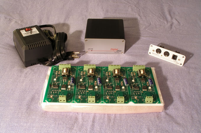
After operating on numerous layouts for more than twenty-five years, I selected Digital Command Control for my layout to facilitate more prototypical operation. I purchased the Lenz Set 100 with additional LH 90 throttles, and added CVP Products T9000E wireless throttles and RX900AL receiver for walkaround control. Pictured at left: DCC Specialties Magna Force MF615 Power Supply, Lenx LVZ100 Command Station, Lenz LA152 Xpress Net Adapter Plates for fascia, DCC Specialties PSX4 Circuit Breaker Modules.
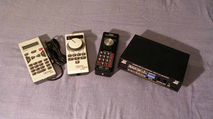
From Left to Right: Lenz LH 100 Dispatcher's Throttle (for programming), Lenz LH 90 Engineer's Throttle (for operating), CVP Products T9000E wireless throttle for walkaround control, and CVP Products RX900AL receiver specifically for use with the Lenz DCC system. The wireless throttle and receiver are shown here without their antennas. All of these throttles have proven to be highly reliable and continue to perform well years later due to their high build quality.
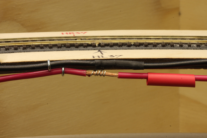
This sequence of photographs illustrates the sequence in making wiring connections for a DCC layout.
I selected 14AWG stranded wire for my bus wires and 22AWG solid wire for my feeder wires. This choice has worked well.
The feeder wires are wrapped around an exposed portion of the bus wire to provide a mechanical connection,and flux is then applied.
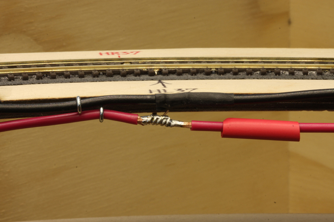
The joint area is then heated with a soldering iron, and solder is applied to complete the joint. A good solder joint is bright and shiny.
Note the short length of heat shrink tubing ready to be moved into place over the solder joint. I pre-position these on the bus wires as I go along, and then move them into place after the solder joint has cooled. In this photograph you can see the tubing on the black bus wire already in place.
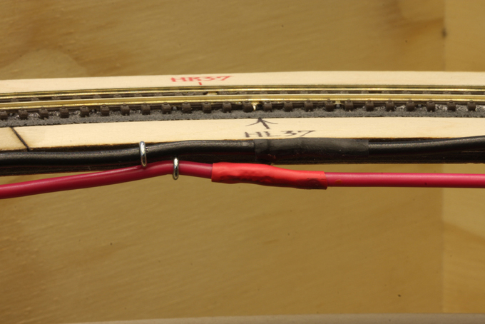
After the solder joint has cooled, the heat shrink tubing is moved into place over the joint.
A heat gun is used to shrink the tubing over the solder joint and lock it into place.
This process eliminates the chance of a short caused by two solder joints on opposing bus wires touching each other.
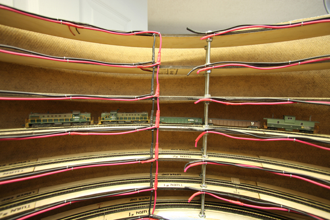
This photograph shows the wiring in the helix after connecting all of the feeder wires to the bus wires. The helix was wired with branches serving each turn. The bus wires are attached to the inside edges of the helix.
When wiring for DCC you can have as many branches as you like, but never a complete circuit or loop. it is also important to ensure that you do not connect any feeder wires to the wrong bus wires. I used black and red wires with the black wire feeding the left rail and the red wire feeding the right hand rail facing north or east.
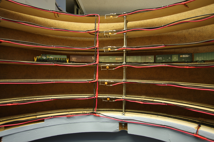
The final step was to terminate the bus wires with a capacitor and resistor in series. This is done to mitigate problems caused by DCC signal reflections along the bus wires. I used HC104/50 .1UF-50V Z5U Ceramic Disc Capacitors and 100R-1W-5% Resistors Carbon 100. I used small clip-on heat sinks to prevent damaging the components during the soldering process.The capacitors and resistors were wired in series at the end of each branch of the helix wiring.
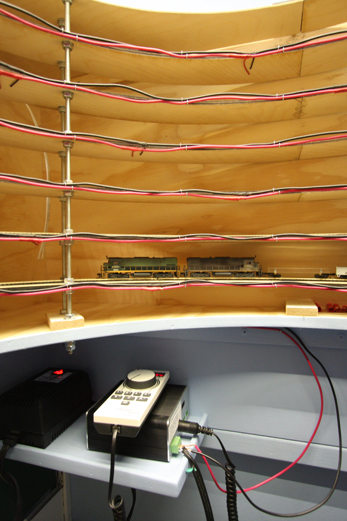
After
initial tests with a DC power pack connected to the helix bus wires, it was
time to connect the Lenz DCC system. This photograph shows the Magna Force
power supply, Lenz command station in place on the shelf provided for them
underneath the helix, together with an LH-90 Engineer's Throttle. At this early
stage track bus wires and the throttle was connected directly to the command
station.
We can also see a test train with two ALCO C-425s operating under DCC power as they begin to climb the helix. The locomotives were fitted with Train Control Systems M4 decoders.
This was the first occasion on which a train moved under DCC power on the layout.
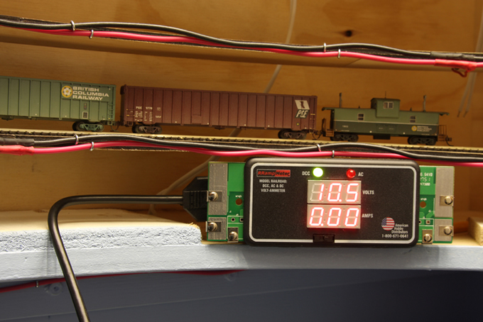
The DCC output voltage has been stepped down to 11 volts
and the change was confirmed with a Ramp Meter which I purchased from Tony's
Train Exchange. This special meter is the only one which can correctly measure
current and voltage on a DCC layout due to the unique wave forms present.
I purchased one Ramp Meter for permanent
installation on the layout and another to be used around the layout as required
to measure any drop in current or voltage.
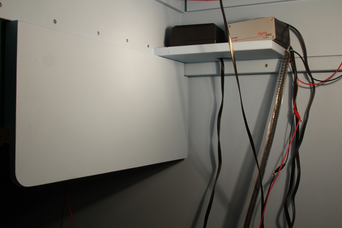
The next step was to create a circuit breaker panel underneath the helix next to the DCC system. This plywood board is removable so that all of the delicate wiring work for the circuit breakers could be done on the workbench. The board needed to be large enough to accommodate eight circuit breakers, terminal blocks and all of the associated wiring.
After painting and a test fit, the board was removed to the workbench for installation of the various components and wiring.
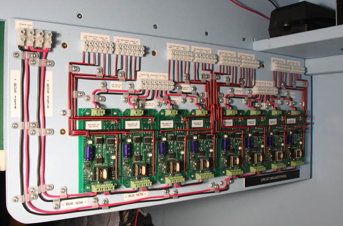
The next step was to mount the circuit breakers (two PSX4 modules from DCC Specialties) using #4 round head wood screws and nylon spacers, and also to mount barrier strips for the wiring connections. Next came the track bus wiring, leading from the top left corner down to the circuit breakers and then up to the barrier strips. I then installed the leads for the LED indicators, which also come up to the barrier strips. Here we see the completed panel mounted in place.

The first Ramp Meter was prepared for permanent installation with bus wires attached to either end. This was installed immediately after the command station and ahead of the circuit breakers, and mounted out on the fascia where it could be seen from anywhere in the layout room.
The second Ramp Meter was fitted with a lamp to provide a load when testing current and voltage round the layout.
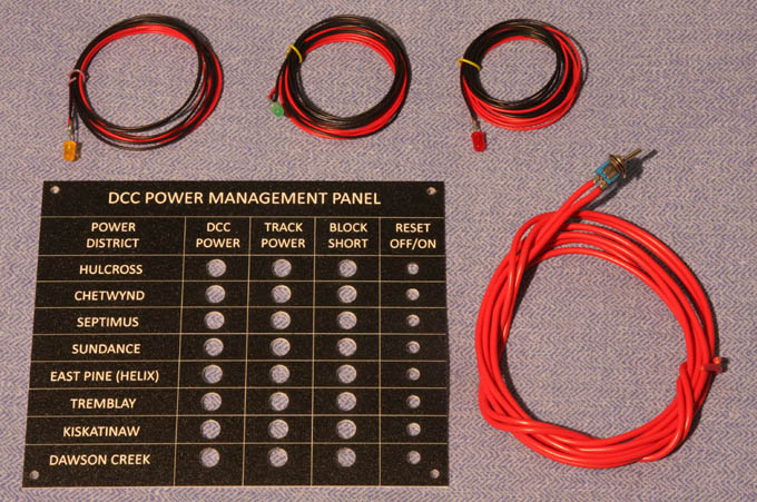
This photograph shows examples of lead wires soldered to the indicator LEDs and reset switches, and the lamicoid Power Management Panel which would house the LEDs and switches for each of the eight power districts around the layout.
The reset switches provide a means of
turning track power off and back on again in each power district, for
maintenance or when trouble shooting. This feature was recommended to me by my
friend Brian Pate.
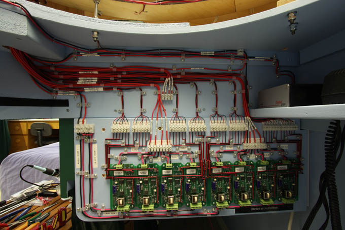
This photograph shows the circuit breaker panel after connecting all of the bus wires up to the reset switches, and the LED indicators up to the Power Management Panel.
The wires along the top run from the command station over to the Ramp Meter and then down to the circuit breaker panel. All of the wiring was identified with a Rhino label maker and the labels were covered with clear shrink tubing.
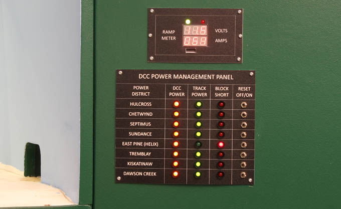
Here we see the Power Management Panel in operation, with seven of the power districts operating normally and the power district #5 indicating a short. The circuit breakers interrupt track power during a short to protect against heat build-up, and they automatically restore power when the short is rectified.
Above the Power Management Panel, we can see the permanent Ramp Meter in operation and displaying a continuous readout of current and voltage.
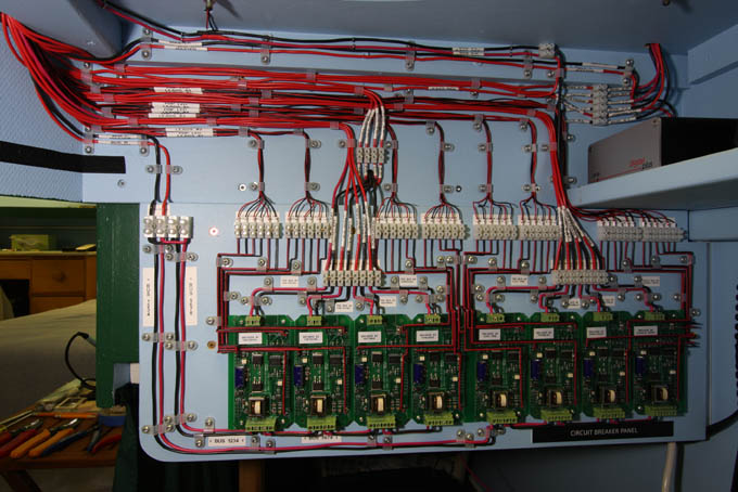
The next
phase of track bus wiring was to extend the bus wires from the circuit breaker
panel out to the underside of the lower and upper decks, from where they will
continue their runs around the layout.
The bus wires for the lower deck are routed to the underside of the lower deck through a hole just above the circuit breaker panel, and those for the upper deck are routed through a hole above the command station and up inside the helix.
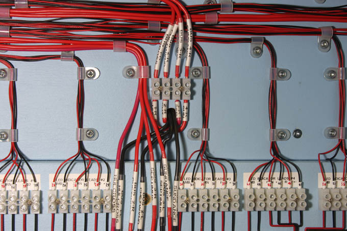
This
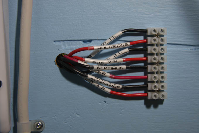
close-up view shows the track bus wires for the lower deck passing through
their hole to the underside of the lower deck.
The red wires are the returns from the reset switches on the Power Management Panel, and the black wire are coming directly from the circuit breaker panel.
This
photograph also offers a close-up view of the labeling method used to identify
all of the wiring.
Here we see the same track bus wires emerging from beneath the lower deck benchwork.
From here the bus wires will continue around the layout underneath the tracks.
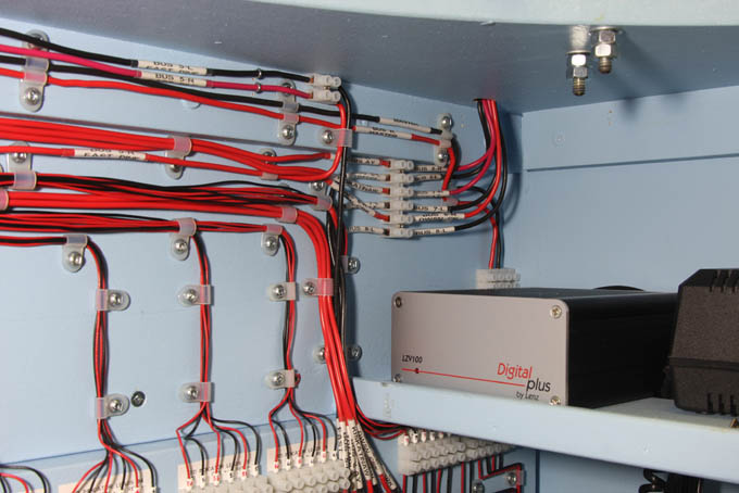
The track bus wires for the upper deck pass through a hole above the command station, and then up inside the helix to the upper deck. The track bus wires for the helix go directly to the helix which is located immediately above.
This
photograph illustrates he use of nylon cable clamps for securing the
wiring, and the use of ferrules for attaching the smaller lead wires
into the terminal blocks.
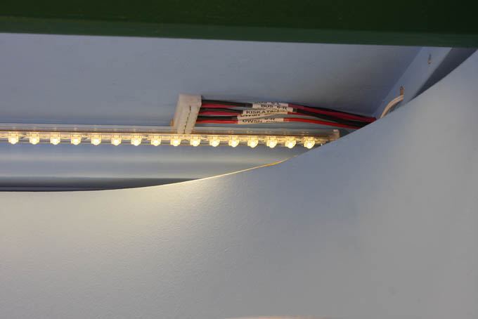
Here we see the same
track bus wires emerging underneath the upper deck benchwork.
From here the bus wires will continue around the layout underneath the tracks.
Again, the bus wires are brought into a barrier strip for ease of connecting and disconnecting benchwork sections from each other without cutting any wires.
The wires are labeled at each terminal block.
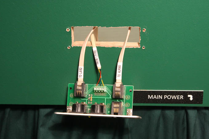
The other part of wiring for a DCC layout is to provide the data bus. With the Lenz system this is referred to as the XpressNet.
A data cable is run from the command station to the LA152 fascia panels around the layout, into which the Lenz throttles may be plugged.
This photograph shows a panel being installed with the data cable connections already made. A crimping tool was used to attach the plugs to the ends of the cables.
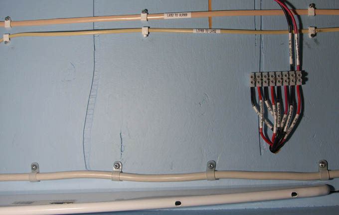
This photograph shows the XpressNet wiring running underneath the lower deck benchwork. It is held in place with plastic clips and is labeled. There is no need to run the XpressNet around the upper deck benchwork; the lower deck plug-ins will suffice.
Also visible are the track bus wires emerging underneath the lower deck, with one of the runs extending onward, and the power cord to the wall.
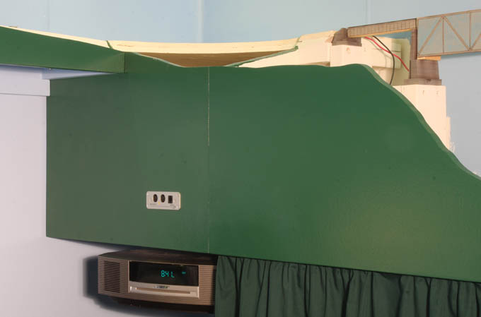
This photograph shows a Lenz LA152 fascia panel mounted in the front of the Highway 97 overpass section of benchwork.
The XpressNet runs to this panel from a panel mounted in the front of the Pine River bridge section.
Adding another panel on this side of the layout provides additional plug-in sockets for the Lenz throttles.
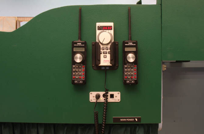
Here we see the LA152 fascia panel on the front of the Pine River bridge section, together with a plastic pocket for the Lenz LH90 throttle.
The two CVP wireless throttles are fitted with Velcro pads for attachment to the fascia when not in use.
This section of fascia has served as the main storage area for throttles to date. Additional throttle storage will be provided in front of Chetwynd Yard after it is built, and the XpressNet is extended around the layout.
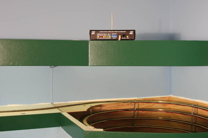
The Lenz LA152 fascia panels provide an option for running branches of he Xpressnet to other locations.
From the panel in front of the Pine River bridge section, a branch of the XpressNet was run up behind the helix to the lighting canopy above for connection to the CVP wireless receiver.
This position high above the layout offers the best reception for the wireless throttles. This particular CVP receiver is designed to connect to the XpressNet.
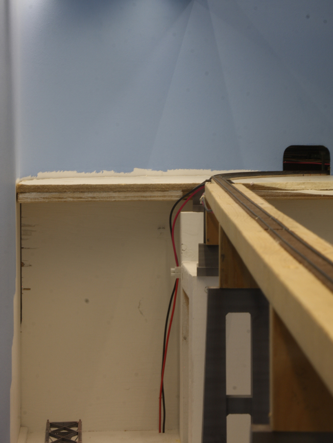
There are three bridges on the layout, and I wanted to devise a system for wiring them in such way as to allow the bridges to be removable without disturbing the connections to the bus wires.
The solution was to run pairs of feeder wires from either end of the bridges down to terminal blocks below, where connections could be easily undone for removal of the spans. From the terminal blocks, the feeder wires continue down to permanent connections with the bus wires, which do not need to be disturbed.
Pictured at left is the Pine River bridge looking eastward toward the helix, with the feeder wires extending down to the terminal block, and then continuing down below the benchwork to the bus wires. This system has proven to be effective in facilitating removal of the bridges on occasion.
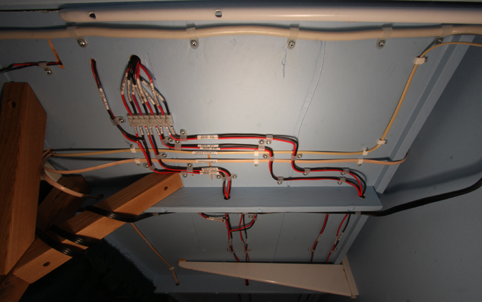
This photograph shows the completion of wiring underneath the lower deck at the east end of the Pine River bridge.
From top to bottom: power cord for main power, track bus wires emerging underneath and extending along the lower deck, and XpressNet cables extending out to the fascia and up behind the benchwork to the wireless receiver above the layout. The wires are secured in place with nylon cable clamps.
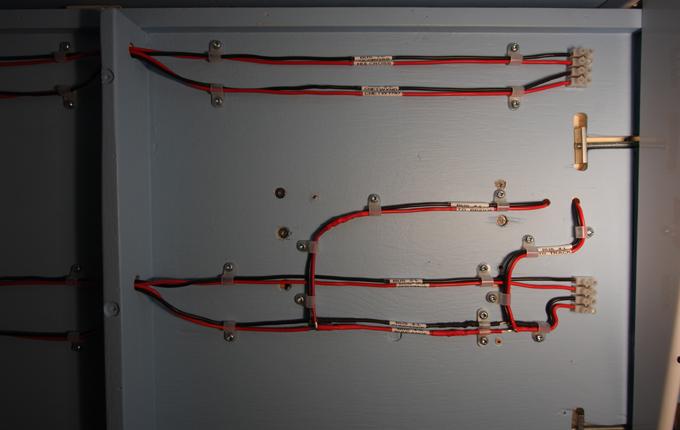
This is the track bus wiring at the other end of the north wall, underneath the Highway 97 overpass section of benchwork. The wires are terminated at a barrier strip in preparation for continuing on to the next section of benchwork.
The two branches of bus wires seen diverging from the bottom runs pass through the benchwork and up to terminal blocks, and then to the highway overpass.
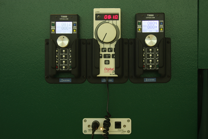
In 2012 CVP Products released a new and improved wireless throttle designated the T5000E, which features an internal antenna. I purchased a variant designated T5000EBL which features a backlit screen.
The new throttles are about the size of an iPhone and have proven comfortable and easy to use. The screen provides a readout of the battery status, channel ID and frequency which is helpful. The new throttles continue to operate very well five years later.
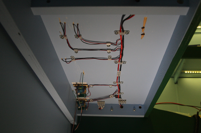
This photograph shows the completion of track bus and feeder wiring for Septimus after completion in 2016. The bus wires extend along the underside from terminal blocks next to the joint with adjacent benchwork.
The other terminal blocks are for future bus runs under this section of the layout which had not been run at the time of this photograph. Also visible are servos and frog juicers for the north switches at Septimus.
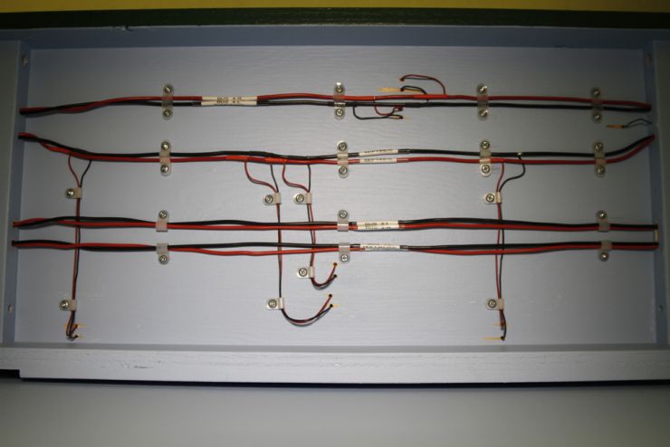
This is another picture of the underside of the lower deck along the west wall after installation of the track bus and feeder wires for Sundance.
From top to bottom in the photograph, we see the runs for Sundance, then Sundance, and then the runs for Chetwynd and Hulcross which are being forwarded along to the next sections of benchwork.
An effort was made to space the various runs apart from each other in order to avoid electrical interference.
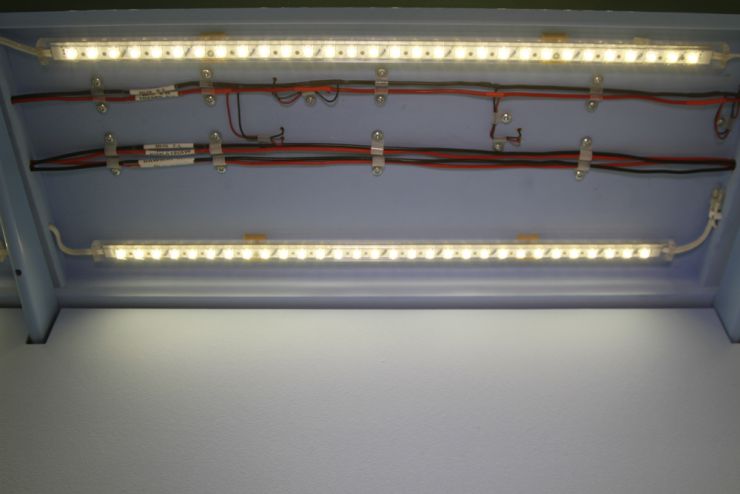
The next section of track to be wired was Tremblay which is located on the upper deck along the north wall.
The top runs in the photograph with feeders attached are for Tremblay, and the runs below are for Kiskatinaw and Dawson Creek which are being forwarded to the next sections of benchwork.
In addition to spacing out the various runs, each pair of bus wires are also twisted at each cross-member in order to minimize electrical issues.
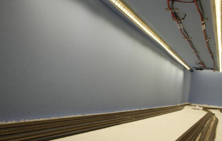
This photograph shows the track bus and feeder wiring for Kiskatinaw underneath the upper deck along the west wall. We can also see the bus runs for Dawson Creek being forwarded to the next sections of benchwork.
This section of benchwork includes the Kiskatinaw River bridge, for which hte feeder wires were routed down to terminal blocks for easy removal, and then down to the bus wires.
After completion of track-laying at Dawson Creek Yard, there was a significant number of feeder wires to be connected to bus wires and secured in place. This was the view looking along the benchwork underneath Dawson Creek Yard upon completion of track-laying.
The black and red wires are the track feeder wires which were soldered to each separate section of track. The green wires are the feeder wires attached to the frogs for each turnout. They will be connected to the frog juicers which regulate polarity for the turnouts.
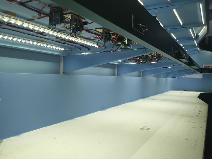
Three months later and the view is completely different. This image was taken from approximately the same angle and location, and shows all of the wiring and turnout control for Dawson Creek Yard in place underneath the upper deck.
This work included running the bus wires for the track and connecting the feeders, installing the servos and Singlets for turnout power and control, running the auxiliary power bus to feed the Singlets, and connecting the Singlets to toggle switches out on the fascia control panels.
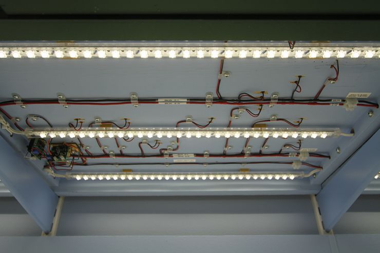
This view underneath the upper deck for Dawson Creek illustrates the completed wiring and turnout control in place. This location is approximately in the middle of the yard.
The track bus was divided into two runs underneath the yard to spread out the connection of feeder wires. The 14 AWG track bus wires can be seen, as well as the smaller 18 AWG auxiliary power bus further in. Note that the LED light strips were mounted on small blocks to allow for the passage of wiring above.
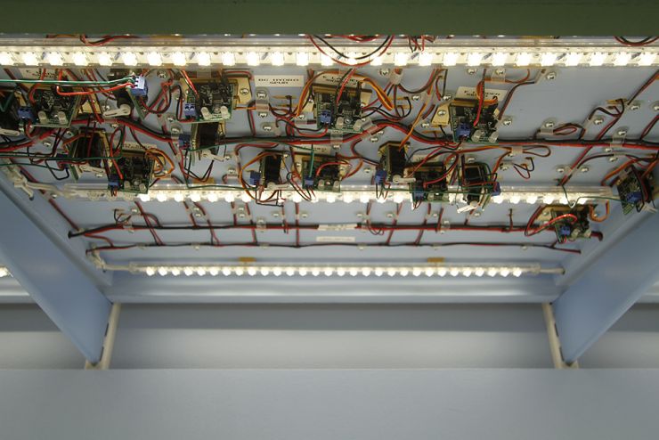
This photograph was taken underneath the upper deck in the vicinity of the east ladder tracks, where there is a large concentration of turnouts.
For each turnout there is a servo mounted on a bracket, with the frog juicer attached to the rear of the bracket. A second bracket accommodates the Singlet servo driver.
The track bus wires and auxiliary power bus wires can also be seen in this image, with the front bus wires altering course to avoid servo installations.

The last phase of wiring work was for Chetwynd Yard which extends along thirteen feet of benchwork. This view looking up at the underside of a section of benchwork underneath Chetwynd Yard, a separate track bus run for a future extension to south staging (Hulcross), and the auxiliary bus for powering the servos.
The unattached feeder wires are for the frog juicers and servos which have yet to be installed. The bus wires are 14 AWG and the feeder wires are 22 AWG.

With completion of Dawson Creek Yard and the pending completion of Chetwynd Yard, the time has come to extend the XpressNet command bus around to the other side of the layout. This will facilitate the use of Lenz throttles in the yard when desired.
The work involved extending the command bus wires around the underside of the lower deck, connecting them to several LA152 fascia plates in front of Chetwynd Yard, and mounting new throttle pockets beside the fascia plates.

The previous photograph shows the fascia plate and throttle pockets at the north end of the yard; this photograph shows a similar installation at the south end of the yard. The fascia plates provide inputs for the throttles and a status light for the command bus.
Both photographs illustrate the provision of storage pockets for the throttles (which required extensions to the fascia to keep the throttles below the level of the layout), and stowage for the uncoupling skewers.
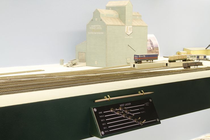
I also provided stowage for uncoupling skewers around the upper deck, but the fascia is not deep enough to accommodate vertical stowage for them. I adopted a suggestion from friend Mark Dance to stow them horizontally using pairs of cup hooks which screw into the fascia.
The uncoupling skewers are located at areas where uncoupling is likely to take place, such as siding switches and yard ladders, and they were mounted directly above the control panels.

I changed out the name plate for MAIN POWER for a new one which incorporates a blue LED indicator light. This LED is powered from the supply for the fan which cools the command station, and is set to come on whenever the Main Power switch is thrown.
I have occasionally left the Main Power on accidentally and the indicator light is intended to help prevent this from happening. The blue LED is sufficiently bright so as not to be missed when on!

A similar indicator light and new name plate were provided for the AUX POWER switch, which is across the room from the MAIN POWER switch. I have been prone to leaving this on as well so the indicator light was needed.
The indicator light is powered from one of the auxiliary bus runs under the layout and is set to come on whenever the Aux Power switch is thrown.
The blue LED is sufficiently bright so as not to be missed when on!
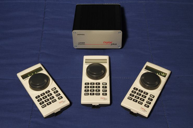
Update 23 December 2019 - I have traded in my existing Lenz DCC LZV100 and LH90 and LH100 controllers for the new Lenz DCC components. The new system comprises the LZV200 command station and LH101 controllers.
The new system offers a host of significant upgrades and reduces the Lenz controllers to one single type which combines the best features of the LH90 and LH100 controllers.
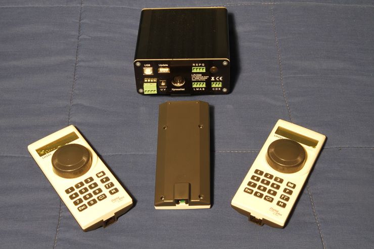
This rear view of the LZV200 command station illustrates several of the new features including a built0-in USB port for computer interface and a port for an update stick which is supplied with the new system.
A wireless version of the LH101 controller is currently in development and is expected in 2020. At that stage I will be able to replace the CVP wireless system and have one type of controller for all operators.
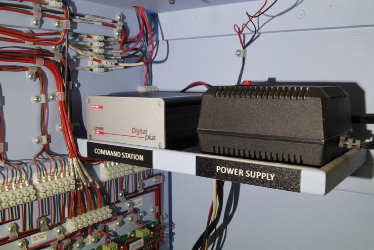
This photograph shows the new LZV200 command station in place underneath the helix on the layout. The various connections were identical to the LZV100 except for the change from a five pin to four pin connector for terminals J, K, U, V.
The existing Magna Force MF615 power supply remains compatible with the new command station.
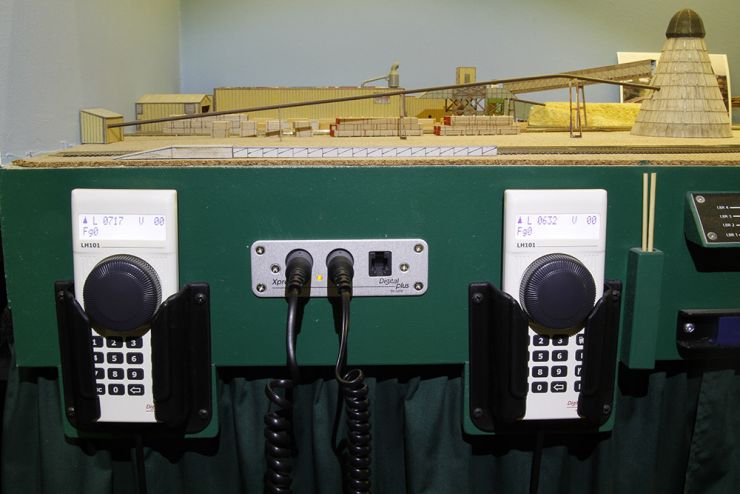
This photograph shows two of the new LH101 controllers connected to the layout. The rotary encoder is used to control the speed steps and is pushed to change direction. It is also used to scroll through the various menus and is pushed to select a menu option. The buttons are used to enter locomotive numbers or select functions. The backlit LCD screen is easy to see and the menus are easy to navigate through. The controllers are ideal for one hand operation.
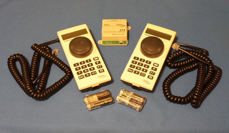
July 2021: I have taken delivery of the new Lenz wireless system, which will replace my CVP wireless system. The new LH101-R throttles are identical to the existing LH101 units except for the battery compartment at the rear. The LTM101 receiver connects to the XpressNet data bus.
The acquisition of the LH101 throttles and now the Lenz wireless system means that where I once had three different types of throttles, I now have one.

